A couple of users have asked me for a guide to laying out their PuzzleLock Sewers to match the example in the product video. I can see how it could be a little confusing until you have enough tiles printed out to be able to play with it and see how you can configure it.

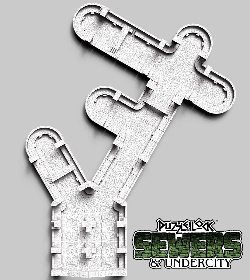
In the video, you can’t really see all of the puzzlelock connections. This is a good thing–unless you are having to freeze frame to figure it out… So here are some call outs for the pieces you need to configure the large area that I show leading to a large arch inspired by the “Cloaca Maxima” of the sewers of ancient Rome.

The normal passageway through the sewers is 6″ across. The “wall” sections (3 types) have a 1″ wide ledge that would be the walkway when the sewers are full of water. Between the walls is a 2″ square tile. There are bridge tiles that can cross the entire span, and “end” tiles that can cap off a passage:

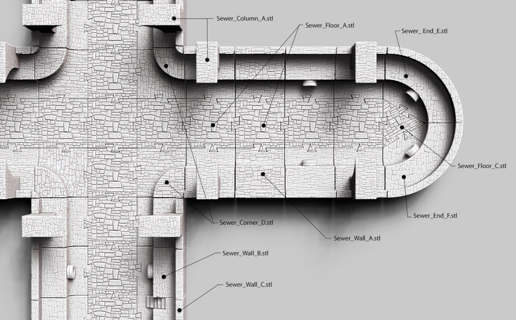

The Sewer_Column_A and Sewer_Column_B should be places symmetrically across from each other on a passageway to create the impression of an arch across the passage (though the height of all pieces is cut off at 70mm).
I hope this is helpful! If you have not purchased the .STL files they are available here for only $19.95

Leave a comment